
URU Key - making decision on power source
The next important step of making autonomous FIDO2 Authenticator device is the power source. In general, I have two options - replaceable or rechargeable batteries.
The replaceable option is the cheapest and most easy to implement. While the coin size cell (CR2032) has a slightly lower voltage (3.0V vs 3.3V) it should provide enough power for the device built on ESP32 microcontroller.

The biggest concern here is - what to do in the situation where I need to authenticate but the battery is already dead? Always have a spare battery? Does not look good, to be honest…
The rechargeable option is better from this point of view. However, it’s more expensive and more complex to implement.

Personally I think the rechargeable option is the best in my case. I have purchased the tiny lithium cell used in hearing assistant devices and a bunch of TP4054 charging ICs. They are tiny and should perfectly fit the small PCB.
And then comes the very interesting question - which connector to use for charging? USB Type C is reversible and easy to connect. The Micro USB connector takes the least space on the PCB. USB A can be found almost everywhere as a universal charging solution but really huge compared to others.
Another important thing for the battery-powered device is a measurement of the battery level. Fortunately, there’s not much to invent here - the nice discussion on the StackOverflow gives a circuitry for that. The simple voltage divider is connected to the ADC input and MOSFET enables/disables it to prevent power loss while voltage is not measured.
So, for me, the general design of the power board is more or less defined. I am going to build a power board featuring tiny LiPol rechargeable battery and USB Type C connector. The circuit should be simple and will not differ very much from the datasheets of the respective ICs.
The schematics of the power board looks as follows:
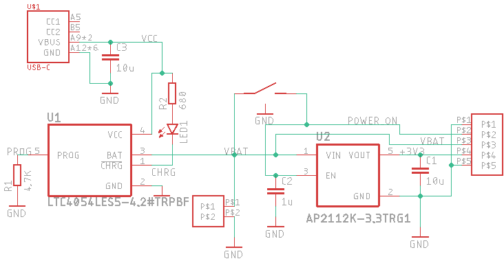
Two ICs are used. AP2112 for the output voltage regulator and LTC4054 for the battery charging. Power switch button enables the output power and then MCU holds the line in the enabled state. Once the device is not used for a certain amount of time it can turn itself off saving battery power. For the charging, the simplified USB Type C connector is used.