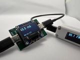
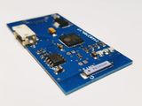
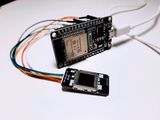
Custom FM Receiver with STM32 and RDA5807: Full Project Breakdown
I built an FM radio receiver. As usual, the goal was to “build something useful and learn something new along the way.” What made this project especially exciting was that it involved working with an STM32 microcontroller—something I hadn’t done before, even though I’ve had several dev boards and programmers lying around for years. I also really wanted to use the headphone wire as the antenna, just like in commercial devices.
The brain of the circuit is the STM32F103 microcontroller. The choice was simple—I already had a few on hand. I had tried to get into STM32 before, but gave up. Luckily, times have changed, and now it’s easy to use the Arduino framework, which handles all the startup configuration. That exact issue is what tripped me up last time.
The first prototype was built using the TEA5767 module—those are everywhere on AliExpress. It’s controlled over I2C, doesn’t need much extra circuitry, and is quite affordable.
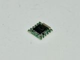
Unfortunately, the module didn’t perform well. The frequency kept drifting, and the signal was constantly dropping out.
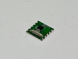
The next attempt was with the RDA5807 module, which didn’t have that issue. It’s pin-compatible with the TEA5767, so you can solder it into the same spot. It doesn’t need an external amplifier either—its built-in amp is good enough to drive headphones. In fact, it makes sense to desolder the chip (along with the crystal) from the module and lay out a custom PCB for it. That’s much easier to do with this chip than with the TEA5767.
I also had to experiment with filtering the antenna and audio signals. The obvious approach—sending the headphone ground and shielding to GND through an inductor and feeding the high-frequency signal to the receiver—worked, but it only picked up two of the strongest stations, and even those had interference. The issue was solved by adding ferrite filters on both audio channels. Turns out there are specific filters made for the 100 MHz band—on the schematic, they’re labeled F1 and F2. That prevents the signal from leaking into the audio amplifier.

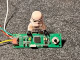
Other than that, the schematic is pretty straightforward: microcontroller, lithium battery power, charging via a TP4054 through a USB Type-C port. The display is an OLED 128×32, and control is handled via a small joystick. Left-right switches stations, up-down controls volume.
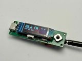
The display shows the tuned frequency, signal strength, and battery level. The chip also supports RDS—text info like the station name and program—but I haven’t gotten it to work properly yet. Most of the time, it just spits out gibberish.
Programming the microcontroller turned out to be very simple — just five wires are needed. And with those same five wires, you get full debugging support: breakpoints, variable inspection, etc. Way more convenient than constantly printing to the console.
Controlling the radio chip, screen, and buttons is all handled with existing libraries — it was just a matter of tying them together in one firmware.
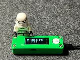
I wrapped the project up with a bright green 3D-printed case. Nothing fancy — just a rectangular box with rounded corners.
The whole thing took a little over six months from start to finish. The first version didn’t work, and I had to go through four or five revisions of the circuit before everything finally worked (mostly) as it should. I still haven’t managed to get the microcontrollers I bought (who knows when or where) to report battery voltage properly—probably knock-offs with an ADC more for show than for actual use. And RDS is still buggy, as mentioned. But honestly? It’s totally usable as-is.
