FPC1020A* Fingerprint Scanners
It’s quite some time since the last update about my awesome FIDO2 Authenticator project. The project did not stop, no. The latest challenging point was the idea that I should not use the external biometric scanner with UART interface but make a built-in one. So, I have ordered a few more biometric scanner modules and, unfortunately, it took several weeks to deliver.
The modules I have found are FPC1020AM and FPC1020AP from the company Fingerprints. They are small and thin capacitive fingerprint scanners with resolution 192x192 pixels at 508dpi and SPI interface. I was quite surprised by how small and thin they are.
Datasheets and general descriptions of the modules can be found in the net, so here is a short summary of what I could discover and how I managed to make them work.
FPC1020AM
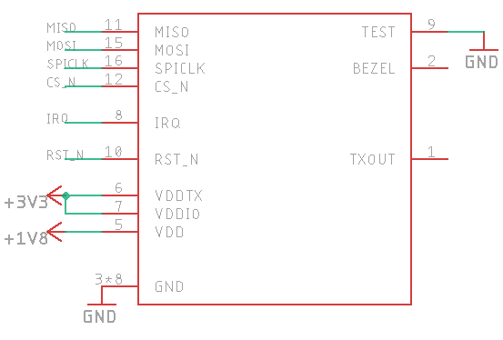
FPC1020AM features flexible cable with flat 16 pin connector. Connector model is BM10NB(0.8)-16DS-0.4V(51) by Hirose.

The pinout for this scanner is as follows:

FPC1020AP
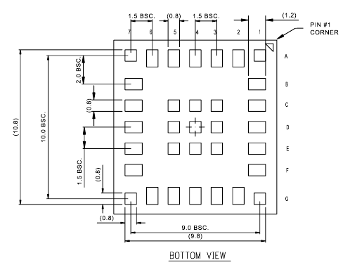
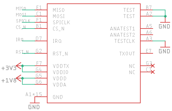
FPC1020AP is the same scanner in LGA package and I’ve spent some time figuring out how to properly connect it.

However, the PDF with package description and datasheet provided by the seller of modules helped me to find the answer.
Pads are organized in a grid with columns numbered from 1 to 7 and rows numbered from A go G.


Warning: both scanners require 1.8V to operate!
Symbols and footprints for both scanners are available in my personal Eagle library.
Test board
To test both kinds of scanners I have designed a very simple board with a pin header and 1.8V voltage regulator.

Connections are very simple and straightforward - from the modules to the pin header. The voltage regulator is LP2985 with ceramic decoupling capacitors.
Boards were manufactured at JLCPCB and one board is used for LGA version of the scanner while the second one is used for the scanner with the flexible cable. Soldering with a hot air gun and mechanical paste went smooth.

The test board is connected to my NodeMCU module as follows:
- GND <-> GND
- +3.3V <-> GND
- RST <-> D2 (GPIO 4)
- IRQ <-> D1 (GPIO 5)
- CS <-> D8 (GPIO 15)
- CLK <-> D5 (GPIO 14)
- MOSI <-> D7 (GPIO 13)
- MISO <-> D6 (GPIO 12)

Arduino sketch
For testing purposes, I have written a simple script using the Arduino framework. It initialises the SPI connection and reads Hardware ID of the scanner.
#include "Arduino.h"

#include "SPI.h"

#define FPC_IRQ 5
#define FPC_RST 4

class FPC1020
{
public:
    void init()
    {
        // Chip select
        pinMode(SS, OUTPUT);
        digitalWrite(SS, HIGH);

        // IRQ / data ready
        pinMode(FPC_IRQ, INPUT);
        digitalWrite(FPC_IRQ, LOW);

        // RST
        pinMode(FPC_RST, OUTPUT);
    }

    void reset()
    {
        digitalWrite(FPC_RST, LOW);
        delay(10);
        digitalWrite(FPC_RST, HIGH);
    }

    uint16_t hardware_id() {
        digitalWrite(SS, LOW);
        SPI.write(0xFC);
        uint16_t status = SPI.transfer16(0x0);
        digitalWrite(SS, HIGH);

        return status;
    }
};

FPC1020 fpc;

void setup()
{
    Serial.begin(115200);
    SPI.begin();

    fpc.init();
    fpc.reset();

    delay(300);

    Serial.println("FPC1020 test");
    Serial.print("Hardware ID: ");
    Serial.println(fpc.hardware_id());
}

void loop()
{
    delay(1000);
}
Properly built and connected board should print out Hardware ID = 522 (0x20A).
Source code for this project is available in my GitHub repository FPC1020-Arduino.
Other commands apart from hardware ID will be implemented with the ESP IDF framework I am using for the main project.
