
Carbon Dioxide Sensor MH-Z19b - Part 1 - Hardware design
Some time ago I have purchased online carbon dioxide (CO2) sensor module MH-Z19b. It’s a cheap and very simple sensor with the UART interface allowing concentration measurement in the range up to 5000ppm.
The normal level of CO2 concentration is considered about 400-1000ppm. Higher levels lead to various negative effects like a feeling of “bad air” and so on.
The concentration of 2000 - 5000 ppm is associated with headaches, sleepiness, and stagnant, stale, stuffy air. Poor concentration, loss of attention, increased heart rate and slight nausea may also be present. In the normal living room without proper ventilation, this concentration can be achieved just within a few hours.
So, I’ve decided to build a simple indicator of dangerous CO2 levels for home use.
First prototype
The first prototype was built using the popular ESP-01 module. The module features ESP8266 MCU with WiFi connectivity and can be easily programmed with Arduino Framework.
Schematic is very simple
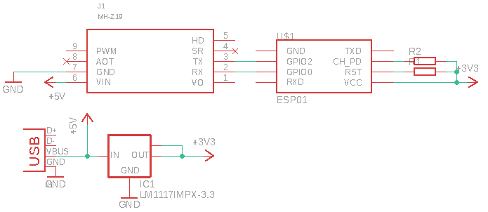
The MCU module is connected to the MicroUSB connector and sensor module with a few wires. Power capacitors were omitted.

This design is extremely simple but allows us to check if the module is working and start to develop firmware code.
For the firmware, I have used the Arduino framework without any additional libraries. Values were read with the software UART and printed out to the debug console. The code looks like
// ...

SoftwareSerial co2(0, 2);

void setup() {
  // ...
  co2.begin(9600);
}

int co2ppm() {
  static byte cmd[9] = {0xFF, 0x01, 0x86, 0x00, 0x00, 0x00, 0x00, 0x00, 0x79};
  static byte response[9] = {0};

  co2.write(cmd, 9);
  co2.readBytes(response, 9);

  unsigned int responseHigh = (unsigned int) response[2];
  unsigned int responseLow = (unsigned int) response[3];

  return (256 * responseHigh) + responseLow;
}

// ...
Test results were surprisingly satisfying so I have decided to continue with the development.
Second prototype
For the second prototype, I have ordered two-sided PCB from the Chinese manufacturer JLCPCB. Ten PCBs cost only $2 which is very affordable for building simple prototypes. The manufacturing process and delivery took around three weeks.

To make the device smaller the sensor module is connected “upside-down”. Space underneath is occupied by the power supply. The MCU module ESP-12e is located on the other side of the PCB. For indication, I use RGB LED module WS2812b.

The device is powered with USB type A connector and can be connected directly to any suitable charger.

The programming and debugging connector are omitted. I have soldered wires from the NodeMCU module directly to the ESP-12e, then flashed simple firmware with OTA upgrade feature. The following flashing was done via WiFi only.